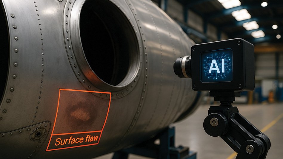
Rivets are small components, but they play a critical role in maintaining the structural integrity of aircraft assemblies. With thousands of fasteners distributed across fuselages, wings, doors, frames, panels, and other structures, manually checking every location can be repetitive and difficult. Detection of Missing and Damaged Aircraft Rivets is therefore becoming an important application for AI-powered machine vision and robotic inspection in aerospace manufacturing and maintenance.
A modern inspection system can combine industrial cameras, precision lighting, robotic positioning, AI-based image analysis, and digital reporting. Instead of depending entirely on an inspector to visually examine every fastener, the system can systematically visit predefined rivet locations and evaluate each one against established inspection criteria.
Why Rivet Inspection Is a Difficult Task
Aircraft structures are rarely simple flat surfaces. Rivets can be positioned on curved fuselage sections, wing skins, frames, access panels, doors, bulkheads, and other three-dimensional assemblies.
A single component may contain different rivet sizes, types, orientations, and installation conditions. Some locations can also be recessed or difficult to access.
Surface reflection adds another challenge. Aluminum, titanium, painted surfaces, primers, coatings, and sealants can produce glare or shadows that change the appearance of a rivet. A small defect may be clearly visible under one lighting direction but almost invisible under another.
For inspectors performing repetitive examinations across hundreds or thousands of locations, maintaining consistent attention can also be challenging.
What Can Automated Vision Detect?
An AI-based inspection system can be configured according to the specific aerospace application and approved acceptance criteria.
Depending on image quality and inspection requirements, visible conditions may include:
- Missing rivets
- Cracked or chipped rivet heads
- Dents and gouges
- Surface scoring
- Deformed rivet heads
- Incorrectly seated rivets
- Tilted rivets
- Incorrect rivet types
- Abnormal head dimensions
- Visible cracks around rivet locations
- Local surface deformation
- Sealant irregularities
- Foreign material or contamination
The objective is not simply to identify whether a circular object exists. The system can evaluate the expected rivet position, appearance, geometry, and surrounding surface condition.
How Robotic Rivet Inspection Works
Robotics can solve one of the biggest problems associated with inspecting large aircraft structures: camera coverage.
A robot or collaborative robot can carry the camera and lighting assembly around the component. At each inspection position, it moves to a predefined pose and captures one or more images.
A typical workflow can include:
1. Part identification:
The system identifies the aircraft component using a barcode, data-matrix code, RFID, production-system signal, or operator selection.
2. Recipe selection:
The appropriate inspection recipe is loaded based on the part or assembly variant. This can include rivet coordinates, robot paths, camera settings, lighting, AI model, and inspection thresholds.
3. Part localization:
Reference features or sensors can determine the actual position of the component so that the robotic inspection path can be aligned correctly.
4. Robotic imaging:
The robot moves the imaging system from one rivet location to another while maintaining the required viewing angle and working distance.
5. AI analysis:
The captured images are analyzed to determine whether each rivet meets the defined visual criteria.
6. Reporting:
Results are linked to the physical location of the rivet and stored for review and traceability.
The Importance of Controlled Illumination
Lighting is often just as important as camera resolution.
Highly reflective aircraft surfaces can generate highlights that obscure scratches, cracks, dents, and other abnormalities. Automated systems can therefore use different illumination strategies depending on the inspection location.
Coaxial lighting can provide controlled illumination for relatively flat surfaces. Low-angle lighting can emphasize raised edges and surface irregularities. Dome lighting can reduce harsh reflections on curved components, while polarized lighting can help control glare.
Multiple lighting directions can also be used to capture several views of the same rivet. This provides the AI model with more visual information when a defect is difficult to identify from a single image.
Combining 2D Vision With 3D Measurement
Conventional cameras are highly effective for presence checks and visible appearance defects, but some rivet conditions involve geometry rather than appearance.
For example, determining whether a rivet is excessively raised, recessed, or incorrectly seated may require dimensional information.
A 3D laser profiler or structured-light sensor can provide measurements such as:
- Rivet-head height
- Flushness
- Countersink depth
- Head geometry
- Local deformation
- Gap dimensions
- Raised edges
A hybrid inspection system can therefore use 2D AI vision for appearance-based inspection and calibrated 3D sensing for geometric verification.
AI and Rule-Based Inspection Can Work Together
AI does not necessarily need to replace conventional machine vision.
Rule-based algorithms can be effective for clearly defined parameters such as rivet position, diameter, circularity, and distance from a reference feature.
AI becomes particularly useful when the appearance of a defect is irregular or when acceptable surface variation makes fixed rules difficult to maintain.
A combined approach can use dimensional rules for measurable characteristics, AI classification for complex visual defects, anomaly detection for unexpected conditions, and 3D measurement for height or depth.
This combination can create a more flexible inspection architecture.
Creating a Digital Defect Map
One major advantage of automated inspection is the ability to connect every result to its physical position.
If a damaged rivet is detected, the system can record the rivet coordinate, defect category, inspection image, AI confidence, and relevant measurement data.
Quality personnel can then view a digital defect map instead of manually searching across the entire component.
Inspection records can also contain the part number, serial number, inspection recipe, AI-model version, inspection date, and individual rivet results. These records can support quality investigations, audits, rework, and process improvement.
Important Limitations
Automated vision should not be treated as a universal replacement for aerospace inspection methods.
A camera-based system primarily evaluates visible or optically measurable conditions. It cannot independently confirm hidden cracks, internal rivet deformation, joint strength, subsurface material conditions, or other characteristics that require approved nondestructive testing or engineering evaluation.
Inspection criteria should therefore be established using applicable engineering drawings, OEM requirements, customer specifications, and approved aerospace procedures.
Building a Reliable AI Inspection System
The quality of an AI model depends heavily on the quality and diversity of its training data.
A robust dataset should include acceptable rivets as well as missing rivets, different damage types, different defect severities, rivet variations, surface finishes, coatings, sealant conditions, lighting changes, and realistic examples of contamination or false defects.
The system should then be validated using independent production data rather than relying only on training images.
Performance should be evaluated using meaningful measures such as defect detection rate, false-accept rate, false-reject rate, repeatability, and performance across different rivet types and aircraft variants.
The Future of Automated Aircraft Rivet Inspection
As aerospace manufacturing moves toward greater digitalization, robotic vision provides an opportunity to transform repetitive rivet inspection into a structured, data-driven process.
Robots provide consistent coverage, machine vision captures detailed images, AI assists with complex defect classification, 3D sensors provide geometric information, and digital software connects individual inspection results to the complete component record.
The most effective systems will not simply automate the act of taking photographs. They will combine robotics, optics, illumination, AI, measurement, inspection recipes, and traceability into a coordinated quality-control workflow.
For aerospace manufacturers and MRO organizations, this approach can provide more consistent inspection coverage while allowing qualified personnel to focus their attention on complex findings and engineering decisions.
About the Author